- 您现在的位置:买卖IC网 > Sheet目录3819 > PIC18F2580-I/ML (Microchip Technology)IC PIC MCU FLASH 16KX16 28QFN
MCP2515
DS21801F-page 54
2010 Microchip Technology Inc.
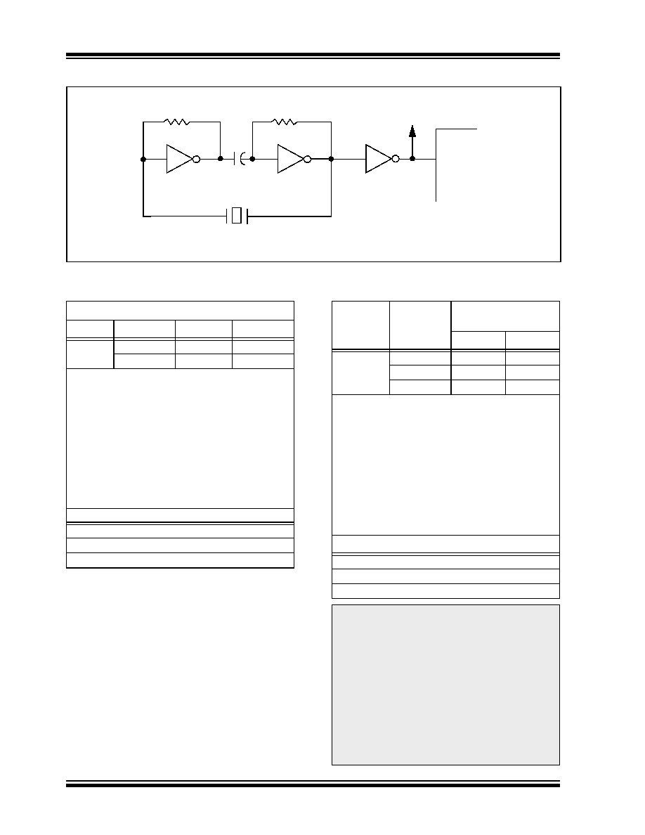
FIGURE 8-3:
EXTERNAL SERIES RESONANT CRYSTAL OSCILLATOR CIRCUIT(1)
TABLE 8-1:
CAPACITOR SELECTION FOR
CERAMIC RESONATORS
TABLE 8-2:
CAPACITOR SELECTION FOR
CRYSTAL OSCILLATOR
330 k
Ω
74AS04
MCP2510
OSC1
To Other
Devices
XTAL
330 k
Ω
74AS04
0.1 mF
Note 1: Duty cycle restrictions must be observed (see Table 12-1).
Typical Capacitor Values Used:
Mode
Freq.
OSC1
OSC2
HS
8.0 MHz
27 pF
16.0 MHz
22 pF
Capacitor values are for design guidance only:
These capacitors were tested with the resonators
listed below for basic start-up and operation. These
values are not optimized.
Different capacitor values may be required to
produce acceptable oscillator operation. The user
should test the performance of the oscillator over the
expected VDD and temperature range for the
application.
See the notes following Table 8-2 for additional
information.
Resonators Used:
4.0 MHz
8.0 MHz
16.0 MHz
Osc
Type(1)(4)
Crystal
Freq.(2)
Typical Capacitor
Values Tested:
C1
C2
HS
4 MHz
27 pF
8 MHz
22 pF
20 MHz
15pF
Capacitor values are for design guidance only:
These capacitors were tested with the crystals listed
below for basic start-up and operation. These values
are not optimized.
Different capacitor values may be required to
produce acceptable oscillator operation. The user
should test the performance of the oscillator over the
expected VDD and temperature range for the
application.
See the notes following this Table for additional
information.
Crystals Used(3):
4.0 MHz
8.0 MHz
20.0 MHz
Note 1:
While higher capacitance increases the
stability of the oscillator, it also increases
the start-up time.
2:
Since each resonator/crystal has its own
characteristics, the user should consult
the resonator/crystal manufacturer for
appropriate values of external
components.
3:
RS may be required to avoid overdriving
crystals with low drive level specification.
4:
Always verify oscillator performance over
the VDD and temperature range that is
expected for the application.
发布紧急采购,3分钟左右您将得到回复。
相关PDF资料
PIC16LF877A-I/L
IC MCU FLASH 8KX14 EE A/D 44PLCC
PIC32MX340F256H-80V/PT
IC MCU 32BIT 256KB FLASH 64TQFP
PIC18F4553-I/PT
IC PIC MCU FLASH 16KX16 44TQFP
PIC16F876-20I/SP
IC MCU FLASH 8KX14 EE 28DIP
PIC24HJ128GP210-I/PF
IC PIC MCU FLASH 128KB 100TQFP
PIC18F2580-I/SP
IC PIC MCU FLASH 16KX16 28DIP
DSPIC33FJ128MC706-I/PT
IC DSPIC MCU/DSP 128K 64TQFP
PIC16F877-20/P
IC MCU FLASH 8KX14 EE 40DIP
相关代理商/技术参数
PIC18F2580-I/SO
功能描述:8位微控制器 -MCU 32 KB FL 1536 RAM 25 I/O RoHS:否 制造商:Silicon Labs 核心:8051 处理器系列:C8051F39x 数据总线宽度:8 bit 最大时钟频率:50 MHz 程序存储器大小:16 KB 数据 RAM 大小:1 KB 片上 ADC:Yes 工作电源电压:1.8 V to 3.6 V 工作温度范围:- 40 C to + 105 C 封装 / 箱体:QFN-20 安装风格:SMD/SMT
PIC18F2580-I/SP
功能描述:8位微控制器 -MCU 32 KB FL 1536 RAM 25 I/O RoHS:否 制造商:Silicon Labs 核心:8051 处理器系列:C8051F39x 数据总线宽度:8 bit 最大时钟频率:50 MHz 程序存储器大小:16 KB 数据 RAM 大小:1 KB 片上 ADC:Yes 工作电源电压:1.8 V to 3.6 V 工作温度范围:- 40 C to + 105 C 封装 / 箱体:QFN-20 安装风格:SMD/SMT
PIC18F2580T-I/ML
功能描述:8位微控制器 -MCU 32 KB FL 1536 RAM 25 I/O RoHS:否 制造商:Silicon Labs 核心:8051 处理器系列:C8051F39x 数据总线宽度:8 bit 最大时钟频率:50 MHz 程序存储器大小:16 KB 数据 RAM 大小:1 KB 片上 ADC:Yes 工作电源电压:1.8 V to 3.6 V 工作温度范围:- 40 C to + 105 C 封装 / 箱体:QFN-20 安装风格:SMD/SMT
PIC18F2580T-I/SO
功能描述:8位微控制器 -MCU 32 KB FL 1536 RAM 25 I/O RoHS:否 制造商:Silicon Labs 核心:8051 处理器系列:C8051F39x 数据总线宽度:8 bit 最大时钟频率:50 MHz 程序存储器大小:16 KB 数据 RAM 大小:1 KB 片上 ADC:Yes 工作电源电压:1.8 V to 3.6 V 工作温度范围:- 40 C to + 105 C 封装 / 箱体:QFN-20 安装风格:SMD/SMT
PIC18F2585-E/SO
功能描述:8位微控制器 -MCU 48KB 3328 RAM w/ECAN RoHS:否 制造商:Silicon Labs 核心:8051 处理器系列:C8051F39x 数据总线宽度:8 bit 最大时钟频率:50 MHz 程序存储器大小:16 KB 数据 RAM 大小:1 KB 片上 ADC:Yes 工作电源电压:1.8 V to 3.6 V 工作温度范围:- 40 C to + 105 C 封装 / 箱体:QFN-20 安装风格:SMD/SMT
PIC18F2585-E/SP
功能描述:8位微控制器 -MCU 48KB 3328 RAM w/ECAN RoHS:否 制造商:Silicon Labs 核心:8051 处理器系列:C8051F39x 数据总线宽度:8 bit 最大时钟频率:50 MHz 程序存储器大小:16 KB 数据 RAM 大小:1 KB 片上 ADC:Yes 工作电源电压:1.8 V to 3.6 V 工作温度范围:- 40 C to + 105 C 封装 / 箱体:QFN-20 安装风格:SMD/SMT
PIC18F2585-H/SO
功能描述:8位微控制器 -MCU 48 KB Flash 3328 RAM 25 I/O w/ECAN RoHS:否 制造商:Silicon Labs 核心:8051 处理器系列:C8051F39x 数据总线宽度:8 bit 最大时钟频率:50 MHz 程序存储器大小:16 KB 数据 RAM 大小:1 KB 片上 ADC:Yes 工作电源电压:1.8 V to 3.6 V 工作温度范围:- 40 C to + 105 C 封装 / 箱体:QFN-20 安装风格:SMD/SMT
PIC18F2585-H/SP
功能描述:8位微控制器 -MCU 48 KB Flash 3328 RAM 25 I/O w/ECAN RoHS:否 制造商:Silicon Labs 核心:8051 处理器系列:C8051F39x 数据总线宽度:8 bit 最大时钟频率:50 MHz 程序存储器大小:16 KB 数据 RAM 大小:1 KB 片上 ADC:Yes 工作电源电压:1.8 V to 3.6 V 工作温度范围:- 40 C to + 105 C 封装 / 箱体:QFN-20 安装风格:SMD/SMT